Phoenix Ambulatory Blood Pressure
Monitor Project
Sub-project: Piezo Film Pulse Sensor
Sub-project: Piezo Film Pulse Sensor
Project Description
The purpose of the piezo film pulse sensor project is to identify and build a reliable, low power, low cost blood flow sensor. The sensor is intended for two proposed designs for the ambulatory blood pressure monitor (ABPM). They are: (a) an oscillometric cuff design (as a Korotkoff sound sensor) and (b) the blood flow velocity design. The project includes the following deliverables:
- Selection of the piezo film sensing element(s).
- Design of a sensing circuit, including filtering and amplification stages.
- Layout and fabrication of a small, low noise circuit board.
- Bill of material
- Evaluation of the completed sensor system.
- Public invention disclosure and release.
- A written report.
Piezo Film Sensor Element
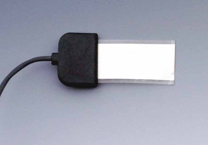
The piezo film sensor element selected for this test was the SDT1-028K made by Measurement Specialties, Inc. It was selected because (a) it is very sensitive to low level mechanical movements, (b) it has an electrostatic shield located on both sides of the element (to minimize 50/60 Hz AC line interference), (c) it is responsive to low frequency movements in the 0.7 - 12 Hz range of interest, (d) the foil size was about right (1 inch / 2.54 cm long) and (e) it has an integral connector and cable for simple connections. The sensor is shown in Figure 1. An RG-174 BNC connector was attached to the opposite end of the cable (not shown).

Filter/Amplifier Circuit
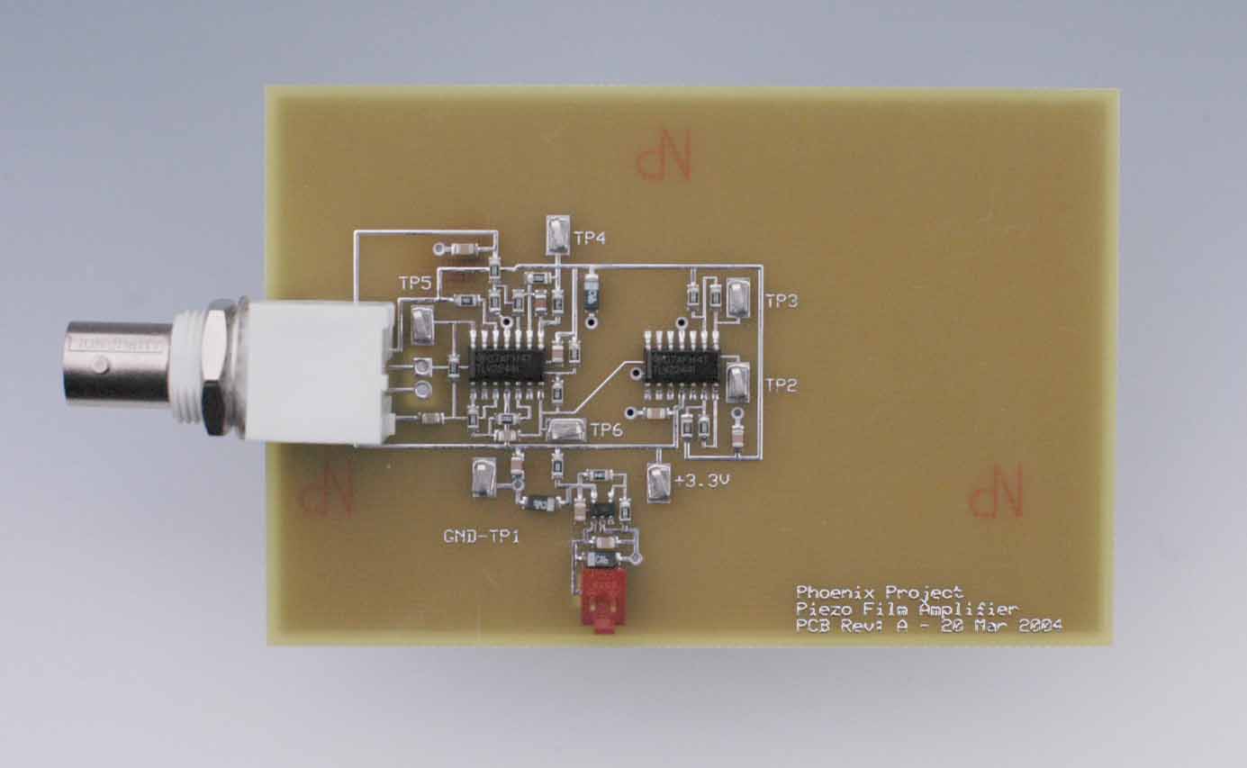
The filter/amplifier circuit shown in Figure 2 was created for the piezo film sensor. It was specifically designed for battery powered operation from three AA or AAA cells (3.6 - 4.5 VDC), and consumes just 100 uA of current. The BNC connector located on the left side of the board connects to the piezo film sensor. The output is monitored with oscilloscope probe(s) via test points located on the board. The board dimensions are 2.5 inch (6.4 cm) x 3.8 inch (9.7 cm).

The circuit has a three-pole low pass filter with a lower (-3 dB) cutoff frequency at about 12-13 Hz. The main purpose of the low-pass filter is to prevent unwanted 50/60 Hz AC line interference from entering the sensor. However, the piezo film element has a wide band frequency response so the filter also attenuates any extraneous sound waves or vibrations that get into the piezo element. The DC gain is about +30 dB. Click here to see the Bode plot of the circuit (i.e. the frequency response).
The circuit has a very high input impedance. Applications notes from Measurement Specialties, Inc. report that the low-end frequency response of the piezo film can be lowered from 5-6 Hz to 0.7 Hz by using a 10 Megohm or higher input impedance. The front end of the filter/amplifier circuit uses an op-amp follower in parallel with a 10 Megohm parallel resistor.
Complete documentation for the circuit is given here, including
a schematic diagram,
bill of material (BOM)
and PCB artwork. All parts (except for the PCB artwork) can be
ordered on-line from Digi-key Corporation at www.digi-key.com.
The PCB artwork can be modified and ordered on-line from ExpressPCB
at www.expresspcb.com.
Just download their free CAD software and the board artwork file
named PiezoAmp.pcb. The
board conforms to the specifications for their low cost 'miniboard'
service. The board assembly uses surface mounted components and
can be hand assembled with the aide of a small soldering iron
and a microscope.
Wrist Pulse Response
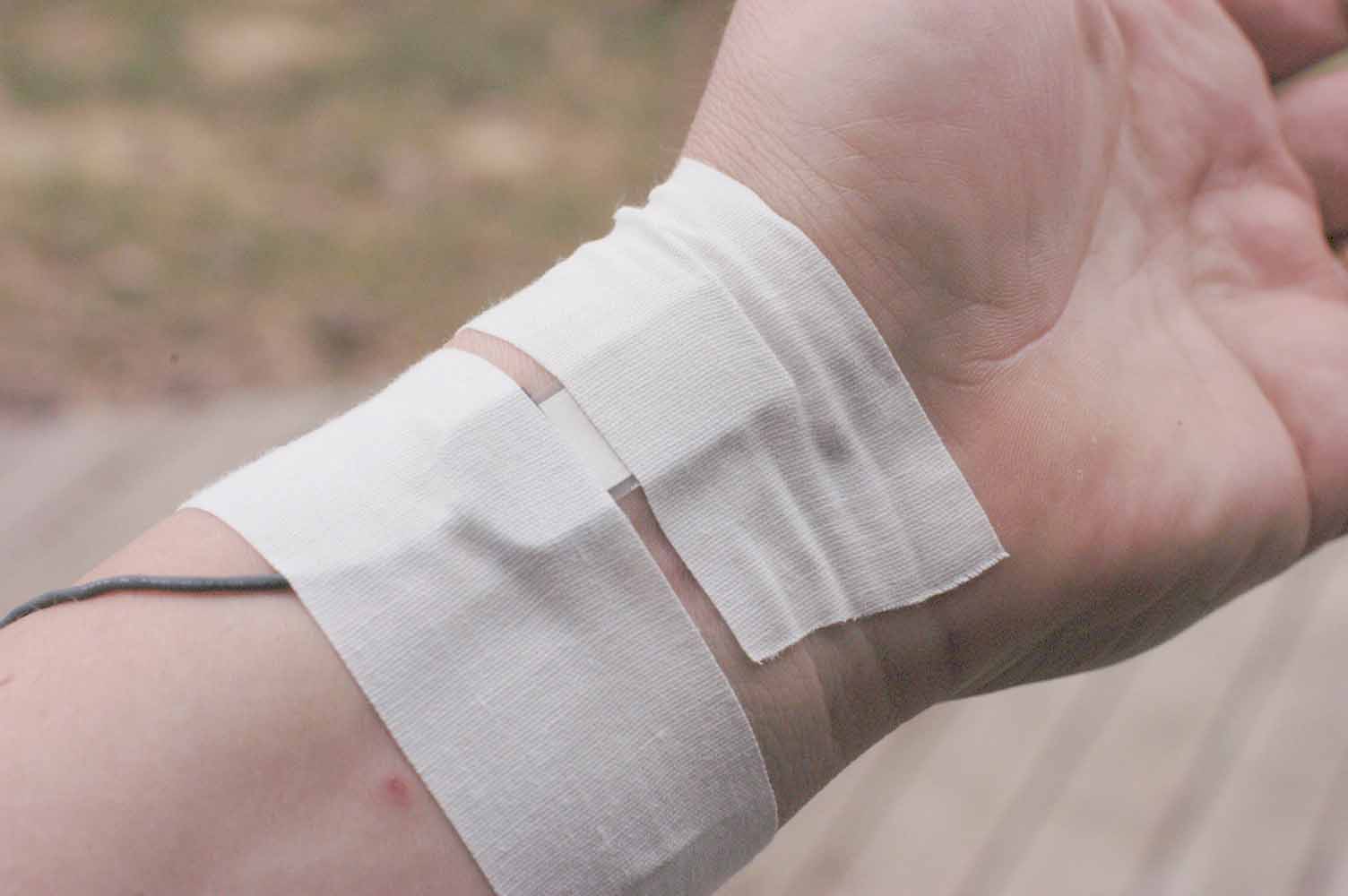
The piezo film was attached to the wrist with cloth athletic tape. The sensor was placed over the pulse point as shown in Figure 3. The adhesive on this tape is designed to be attached to the skin, and is breathable. It's a fairly weak adhesive which also allows the tape to be removed without damage to the piezo element.

Figures 4 and 5 signal response from the filter/amplifier circuit when the sensor is placed over the wrist. Figure 4 is a single sweep waveform as obtained from an HP 54615B storage oscilloscope. Figure 5 uses the same configuration, except that the output signal is averaged over 64 waveform samples. The vertical and horizontal scales for the two waveforms are identical, with a horizontal sweep of 200 mS/div, and a voltage gain of 100 mV/div. All measurements were obtain at test point TP3 shown on the PCB schematic diagram.


Waveform averaging is a well known noise reduction technique.
It reinforces the waveform of interest by minimizing the effect
of any random noise. These pulses were obtained when the arm
was motionless. If the arm was moved while capturing the data
the waveform did not look nearly as clean. That's because motion
of the arm causes the sonic vibrations to enter the piezo film
through the arm or by way of the cable.
Mid-arm Response
The piezo sensor was moved from the wrist to the mid forearm area. The response there was less dramatic as shown in Figure 6. In this case the piezo film is probably picking up the acoustic sound wave rather than any physical motion of the skin surface. This is an area that needs improvement because the acoustic sound waves are probably more valuable in the measurement system, because they permit simplified attachment to the skin.

Blood Velocity Response Between Elbow and Wrist
Two identical piezo film sensors and filter/amplifier circuits were configured as a non-invasive velocity type blood pressure monitor. The first sensor was located on the inner left elbow at the same location where Korotkoff sounds are monitored during traditional blood pressure measurements with a spygmometer. The second sensor was located on the left wrist as described above (about 12 inch / 30cm from each other). Figure 7 shows the results.

Correlation Between Pulse Delay & Blood Pressure
The correlation between pulse delay and blood pressure is well known in the art of non-invasive blood pressure monitors. Some of the best descriptions of this phenominon can be found in several US Patents, including those listed in the Phoenix patent references under the heading of Non-invasive Blood Pressure Monitors Using Pulse Velocity Methods. These can be found via the hotlinks located at the top of the same page. Several techniques are described in those patents including relative pulse delay, EKG to pressure pulse delay and pulse width.
One of the best patent references is Chen et. al, US Patent
No. 6,599,251. Besides being an excellent summary of prior art
in the field of non-invasive blood pressure measurement, Chen
descripbes how blood pressure measurements are obtained using
the pulse delay technique, as well as his data correlating pulse
delay and pressure. However, Chen uses optoelectric sensors rather
than the piezo film elements that are shown in this page. It
is believed by the author that good, non-invasive blood pressure
sensors using the techniques described on this page can be designed
around Chen's claims.
Conclusions
The data show that piezo film can simultaneously monitor two pulse signals located at a fixed distance from each other. This forms a two-point blood velocity monitor that can be adapted for the measurement of blood pressure. The data show that a 12 inch (30 cm) span results in a time lag of about 32 milliseconds.
The technique worked quite well, but does need improvement. Additional experimentation is needed. The following ideas have been generated by the Phoenix group:
- Use a smaller piezo element for improved signal-to-noise
ratio.
- Use a piezo cable. It is hoped that this will improve the
sonic sensitivity (over the current sensitivity to mechanical
movement).
- Attenuate extraneous acoustic vibrations that are transmitted
up the cable. Layers of 'Silly-putty', 'fun-tak' and Sorbathane(tm)
are good candidates for sonic absorbing materials that could
be attached to the cable.
- Use an acoustic coupling compound (such as K-Y jelly) between
the skin and the piezo film element.
Addendum
- A commercial varient of this product has been found at Tensys Medical (SanDiego,
CA). Also see US Patents 6,514,211; 6,228,034; 6,176,831.
About This Page
This page is maintained by David
A. Skramsted. It was last updated
on 19 September 2005.
The author(s) provide this information as a public service, and
agree to place any novel and useful inventions disclosed herein
into the public domain. They are not aware that this material
infringes on the patent, copyright, trademark or trade secret
rights of others. However, there is a possibility that such infringement
may exist without their knowledge. The user assumes all responsibility
for determining if this information infringes on the intellectual
property rights of others before applying it to products or services.
(C) 2004-2005 Wade D. Peterson, David A. Skramsted and Daniel
E. Glumac. Copying and distribution of this page is permitted
in any medium, provided this notice is preserved.