Phoenix Ambulatory Blood Pressure
Monitor Project
Sub-project: Impedance Plethysmograph Sensor
Sub-project: Impedance Plethysmograph Sensor
Project Description
A device called an Impedance Plethysmograph measures the impedance of body tissue in response to blood flow. This sub-project attempts to use an impedance plethysmograph sensor to determine when a blood pulse moves past one or more a fixed points. The idea is to measure the blood pressure using one of several pulse velocity methods. Ideally, the sensor would be located on the upper arm at the same relative height as the heart.
An excellent description of the impedance plethysmograph can be found on-line in Bioelectromagnetism by Malmivuo and Plonsey. Another excellent reference is entire March 1989 issue of IEEE Engineering in Medicine and Biology Magazine.
The correlation between pulse delay and blood pressure is well known in the art of non-invasive blood pressure monitors. Some of the best descriptions of this phenomenon can be found in several US Patents, including those listed in the Phoenix patent references under the heading of Non-invasive Blood Pressure Monitors Using Pulse Velocity Methods. These can be found via the hotlinks located at the top of the same page. Several techniques are described in those patents including relative pulse delay, EKG to pressure pulse delay and pulse width.
Two patents that are of particular interest in the field of non-invasive, impedance plethysmograph blood pressure sensors are Asada et al. PATIENT MONITORING FINGER RING SENSOR (US patent No. 5,964,701) and Yang et al. CUFFLESS CONTINUOUS BLOOD PRESSURE MONITOR (US patent No. 6,413,223). Both pertain to the use of impedance plethysmograph sensors that are attached to the ring finger. It is believed by the author that it would be simple to design around the claims of both patents. This makes them ideal candidates for use by the Phoenix project.
Both Asada et al. and Yang et. al use the impedance plethysmograph method to measure blood flow (and velocity). However, both techniques rely on the pulse velocity method which is best described by Chen et. al, CONTINUOUS NON-INVASIVE BLOOD PRESSURE MONITORING METHOD AND APPARATUS (US Patent No. 6,599,251). Besides being an excellent summary of prior art in the field of non-invasive blood pressure measurement, Chen describes how blood pressure measurements are obtained using the pulse delay technique, as well as his data correlating pulse delay and pressure. However, Chen uses optoelectric sensors rather than the impedance plethysmograph shown on this page. It is believed by the author that good, non-invasive blood pressure sensors using an impedance plethysmograph can be designed around Chen's claims.
Initial Experimentation
Some early experiments were conducted on an impedance plethysmograph suitable for an ambulatory blood pressure monitor (ABPM). The initial experimental set-up is shown in Figure 1. There, four circuilar band electrodes were arranged along the upper left fore-arm of a test subject. The electrodes were made from strips of 1/2" adhesive copper (EMI) tape, 3M number 1181 (available on-line from Digi-key). A signal generator was connected to the outer two bands, and an amplifier circuit to the inner two. Smooth-jaw alligator clips connected the electronics to the electrodes. A schematic diagram of the experimental set-up in 'pdf' form is available here.
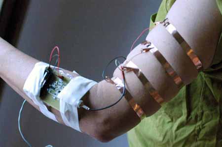
The copper foil tape electrodes worked surprisingly well, especially given the fact that they are extremely low cost. They stuck to the skin very well, did not produce any rash or redness, and appears to have good electrical conductivity between the alligator clips and the skin.
The signal generator was adjusted for sinewave operation over a frequency range of zero to 1.0 MHz, with optimum coupling between the excitation and pick-up circuit at around 100 KHz. Voltages between zero and 3.0 Vrms were used.
The test did not produce satisfatory results in that a pulse wave could not be detected at the amplifier output. The problem appears to be with its low pass filter, which (as it turns out) is inappropriate for this application. An amplifier designed for use with piezo foil was used, which has a low pass cutoff frequency below 20 Hz. A new amplifier will be designed with a bandpass filter around 100 KHz. This will have the benefit of rejecting all noise outside of the passband, especially 50/60 Hz line noise. Furhtermore, the new circuit should include a detector circuit with 20 Hz low pass filter for discrimination of the blood flow signal.
A copy of this page along with relavant attachments was deposited
at the US Patent and Trademark office (using form PTO/SB/95)
on or about 21 Nov 2004.
About This Page
This page is maintained by Wade
D. Peterson. It was last updated
on 21 November 2004.
The author(s) provide this information as a public service, and
agree to place any novel and useful inventions disclosed herein
into the public domain. They are not aware that this material
infringes on the patent, copyright, trademark or trade secret
rights of others. However, there is a possibility that such infringement
may exist without their knowledge. The user assumes all responsibility
for determining if this information infringes on the intellectual
property rights of others before applying it to products or services.
(C) 2004 Wade D. Peterson. Copying and distribution of this page
is permitted in any medium, provided this notice is preserved.